Page 1 of 2
3 yellow alternator wires... connecting
Posted: Sat Jan 02, 2010 7:50 pm
by hardnutdvd
Hi all
Im the proud owner of my first 'proper' bike and chose the VFR400..
It has had charging problem (gasp) and i got the multimeter out today. i downloaded the electroworld help file and step by step test instructions..
whilst testing, i noticed the white 3 pin connector block had been slightly burnt and melted just a tiny amount around one connector. i cleaned and tidied the block as best as possible and it is now pushing out the correct voltage, the battery is taking/holding charge and the reg.rec readings are alright.
this is good news but i am unhappy with the block connector...could i replace and rewire the three yellow wires using 15amp spade/bullet connectors?
Does it HAVE to be the same type of connector block as originally there?
If bullet/spade connectors are unsuitable, what would be a good alternative?
Re: 3 yellow alternator wires... connecting
Posted: Sat Jan 02, 2010 8:41 pm
by fastdruid
Yes you can just use normal spade connectors but I'd advise at least a proper connector block, for example from vehicle wiring products
http://www.vehicle-wiring-products.eu/V ... ectors.php" onclick="window.open(this.href);return false;
Druid
Re: 3 yellow alternator wires... connecting
Posted: Sat Jan 02, 2010 10:16 pm
by DoktorMandrake
If you haven't already, you could check the alternator windings using your multimeter. Set ya mm to continuity and check each of the three phase wires against earth. You should not get continuity. Then set ya mm to ohms and check each of the yellow phase wires against each other. Shouldn't get a reading of any more than 0.8ohms. It's a reasonable way of checking ya alternator without taking the engine casing off. However, I have seen alternators that were burnt out/had problems and still had low res and weren't shorting.
Re: 3 yellow alternator wires... connecting
Posted: Sat Jan 02, 2010 10:33 pm
by Neosophist
Make sure you solder the new terminals on and not just crimp them. They carry a lot of amps and unless there soldered they tend to melt.
Re: 3 yellow alternator wires... connecting
Posted: Sun Jan 03, 2010 10:27 am
by superlite
Why not get rid of terminals/spade plugs all together and just solder them? Jobs a gooden'!
Re: 3 yellow alternator wires... connecting
Posted: Sun Jan 03, 2010 12:28 pm
by hardnutdvd
thanks for all the advice.
Re: 3 yellow alternator wires... connecting
Posted: Sun Jan 27, 2013 11:42 am
by hrc rr
Digging this thread up just to confirm something,
My RHS connector for the alternator is burnt out, so I snipped the wires clean to install a new connector and marked each wire to wire.
But now I'm not sure if I marked the wires correctly, so I just wanted to know if all 3 yellow wires are the same? Or is each yellow wire slightly different and I have to find out which must connect to which?
I looked up the electronic schematics in the NC30 manual and its seems like they're all the same, but just looking to confirm this in case they're not and there's a way of finding the connecting pattern. Also did a search on the site, but this might be such a simple question that it just doesn't come up.
Thanks for any help.
Re: 3 yellow alternator wires... connecting
Posted: Sun Jan 27, 2013 11:53 am
by speedy231278
No, doesn't matter. Each wire comes off of a different winding, but the voltage between any given pair is nominally the same.
Re: 3 yellow alternator wires... connecting
Posted: Fri Mar 15, 2013 12:54 am
by v4hrc
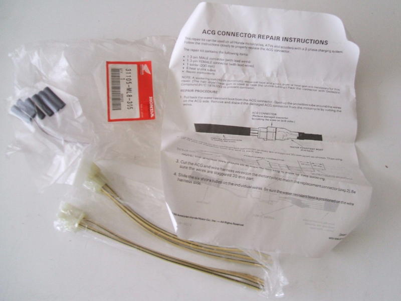
Honda makes a kit for repairing this connection - 31105-ML8-305
http://www.genebitsystems.com/david/Mot ... airKit.jpg
Re: 3 yellow alternator wires... connecting
Posted: Fri Mar 15, 2013 9:18 am
by speedy231278
Never mind, I've done mine now! lol It didn't cost almost £16 either. Still, I guess this kit has the right connector in it, which would mean that it would fit into the bracket rather than have to be tucked underneath.